
Experimental investigation on mechanical properties of new type of marine composite plate with reinforcing ribs and core material in the middle

-
摘要:目的
:面向复合材料的实船应用前景,设计一种泡沫填充的复合材料夹芯夹筋结构(组合厚板)。
方法针对组合厚板各向异性的特点,针对组合厚板顺筋方向和垂直筋方向分别进行三点弯曲试验与拉伸试验,对比该结构不同方向上的强度和模量,重点分析组合厚板在2个方向弯曲载荷下的破坏模式及其失效机制,讨论试件中心位置、胞元筋板数量对其力学性能的影响。
结果结果显示,组合厚板各向异性显著,相较于顺筋方向,结构在垂直筋方向弯曲强度提高了82%,拉伸模量提高了22%;在弯曲载荷下,结构发生初次破坏后承载力大幅降低;在垂直筋方向,初始破坏模式为下面板局部脱粘,在顺筋方向,初始破坏模式为筋板剪切破坏;胞元筋板数量和中心位置对组合厚板弯曲强度影响显著,对其拉伸模量影响较小;在弯曲载荷下,结构初始破坏模式与胞元筋板数量和弯曲中心位置无关;初始破坏时,纤维未出现明显的屈曲、断裂现象,面板、筋板和泡沫之间的粘接强度一定程度上决定了结构的弯曲强度;初始破坏后,试件的损伤过程有所不同。
结论对组合厚板开展力学试验,可为后续复合材料夹芯夹筋板在船海主承力结构上的推广应用提供技术参考。
Abstract:ObjectivesWith the development of shipbuilding technology, composite materials have shown great potential in ship construction due to their excellent properties. However, the application of sandwich structures in ship main load-bearing structures has been limited due to the weak out-of-plane load-bearing capacity. The aim of this study is to design a novel foam-filled composite sandwich structure with reinforcing ribs (combined thick plate) to address this issue and explore its application prospects in ship main load-bearing structures. This research is of great significance for promoting the development of lightweight ships.
MethodsIn this study, a series of mechanical property tests were carried out. First, according to the anisotropic characteristics of the combined thick plate, three-point bending and tensile tests were conducted along and perpendicular to the direction of the reinforcing ribs. For the bending tests, referring to the GB/T
1456 - 2021 standard, four types of bending test specimens were designed. These specimens were divided according to the number of cell reinforcing plates in the direction perpendicular to the ribs and the bending center position in the direction of the ribs. For the tensile tests, with reference to the GB/T1040.5 - 2008 standard, four types of tensile test specimens were designed based on the tensile center position in the direction perpendicular to the ribs and the number of cell reinforcing plates in the direction of the ribs. Each type of specimen had 6 samples tested, and the mechanical property parameters such as bending strength, bending stiffness, and tensile modulus were calculated through specific formulas.ResultsThe experimental results reveal the significant anisotropy of the combined thick plate. In the direction perpendicular to the ribs, the bending strength of the structure is increased by 82% compared with that in the longitudinal direction, and the tensile modulus in the longitudinal direction is 22% higher than that in the perpendicular direction. The number of cell reinforcing plates and the loading center position have a remarkable impact on the bending strength, while having a relatively small effect on the tensile modulus. The adhesive strength between the panel, ribs, and foam plays a crucial role in determining the bending strength of the structure. In terms of failure modes under bending loads, the initial failure mode in the direction perpendicular to the ribs is the local debonding of the lower panel. In the direction of the ribs, it is the shear failure of the reinforcing plate. The number of cell reinforcing plates and the bending center position have no obvious influence on the initial failure mode. After the initial failure, the damage processes of the specimens in different directions are distinct. In the specimens bent in the direction perpendicular to the ribs, the upper panel will locally debond following the lower panel, and the final failure is caused by the complete debonding of one side of the lower panel. In the specimens bent in the direction of the ribs, some specimens fail due to the complete debonding of one side of the lower panel, while in others, the lower panel does not completely debond, and the panel gradually loses its load - bearing capacity during the loading process.
ConclusionsIn conclusion, this research provides a technical reference for the promotion and application of composite sandwich reinforcement plates in ship main load - bearing structures. The obtained data and conclusions can guide the design and optimization of composite structures in shipbuilding, helping to improve the structural performance and safety of ships. It also offers valuable insights for further research on the mechanical properties of composite materials in marine engineering.
-
Keywords:
- composite materials /
- sandwich structure /
- mechanical tests /
- failure mode /
- bend /
- tensile
-
0. 引 言
夹芯结构作为一种轻质多功能复合材料结构,与传统的船用加筋板结构相比具有比强度高、抗冲击性能强、防火隔振性能优异等特点,是一种十分理想的轻量化材料,被广泛应用于船舶上层建筑甲板、雷达平台和潜艇导流罩等船舶与海洋工程结构非承力功能性部件[1],但在船舶主承载结构(如船底板、耐压壳等)上的应用并不理想。
近年来,为了加快高性能材料在船舶主承力结构(船底板、潜艇耐压壳)上的应用,针对各种形式的夹芯结构,如泡沫、波纹、棱柱夹芯等开展了广泛的研究[2-4]。例如,Duarte等[5]针对一种泡沫铝金属夹芯结构开展了三点弯曲试验,结果显示,金属泡沫填充夹芯结构具有良好的吸能能力;Farrokhabadi等[6]制作了多层玻璃钢波纹夹芯板,通过试验和有限元方法研究了其弯曲性能,并指出可以通过多层设计来提高夹芯板的峰值载荷与吸能能力;赵延杰等[7]针对泡沫夹芯板开展了水下接触爆炸试验,研究得出夹芯板的耗能率较实体钢板提高了约5%~8%;陈翀一等[8]对复合材料夹芯板的抗冲击性能展开了研究,发现芯层主要通过压缩变形来吸收冲击能量。可以看出,目前学者们主要是针对夹芯板在能量吸收和典型动态场景下的力学响应开展研究,而对于船舶主承力结构,关注更多的是结构的承载能力,包含结构的极限强度、弯曲刚度、拉伸刚度等。若要实现夹芯结构在船舶主承力结构上的大规模应用,需重点提升夹芯板的面外承载能力。
为了改进传统夹芯结构面外承载力较弱的缺点,一些学者提出了棱柱形[9-10]芯的新概念,即在芯层中设置高强棱柱形夹筋,用以提高结构的强度和刚度。例如,Smardzewski[11]制备一种具有多层棱柱芯的木质夹芯板,相对于传统结构,其抗弯曲能力显著提升。受此启发,本文拟通过真空辅助成型工艺将复合材料板作为加强筋填充至泡沫夹芯板中,提出一种复合材料夹筋夹芯板结构。但该结构组分多元,采用数值仿真方法很难找到合适的失效准则用于模拟复杂多样的失效模式[12],且其在面外载荷的作用下变形破坏机制十分复杂。因此,本文将通过开展力学性能试验测试复合材料夹芯夹筋板的弯曲与拉伸性能,研究胞元筋板数量和中心位置对其力学性能及弯曲破坏行为的影响,以期为后续进一步的设计和应用提供参考。
1. 结构设计与制备
1.1 结构设计
本文提出的复合材料夹芯夹筋板结构(以下简称为“组合厚板”)由上、下2两个厚面板及中间的芯层组成,芯层在填充高性能泡沫的基础上增设了加强筋板,如图1(a)所示。图1(b)所示为组合厚板的代表性胞元及相应的尺寸。由于目前国内外并无严格对应的试验规范要求,因此学者们普遍根据结构特点,通过参考相关规范自行设计试验。本文参考的相关试验标准对试验构件的具体尺寸并未做明确要求,需根据所设计结构的自身结构型式,并结合一定的数值模拟来对组合厚板的尺寸进行设计。复合材料各组分之间复杂的非线性界面关系是数值模拟的难点,因此本文前期的数值仿真对其进行了简化[13],并根据数值仿真结果最终确定了本文所设计复合材料夹芯夹筋结构的尺寸参数:面板厚度5 mm,筋板厚度3.4 mm,铺层方式[(0/90)12/0],共25层;圆弧半径3 mm,铺层方式为[(45/−45)8/45],共17层;筋板宽度15 mm,筋板间距26.25 mm。
![]() 图 1 复合材料夹芯夹筋结构示意图Figure 1. Schematic diagram of composite plate with reinforcing ribs and core material in the middle
图 1 复合材料夹芯夹筋结构示意图Figure 1. Schematic diagram of composite plate with reinforcing ribs and core material in the middle上、下面板及筋板均为高强度的碳纤维增强复合材料(CFRP)层合板,采用T300碳纤维增强乙烯基树脂预浸料制备;内部填充BX-700型泡沫,具有支撑和载荷传递的作用,可进一步提高复合材料夹芯结构的力学性能;面板、筋板和泡沫之间通过Zj-3型粘接胶固定。相关材料的属性见表1和表2[14-15]。
材料 性能 数值 CFRP 纵向弹性模量E1/GPa 125 横向弹性模量E2/GPa 11.3 法向弹性模量E3/GPa 11.3 剪切模量G12,G13,G23/GPa 11.3 泊松比v12,v13,v23 0.3 纵向拉伸强度XT/MPa 2 000 纵向压缩强度XC/MPa 1 000 横向拉伸强度YT/MPa 80 横向压缩强度YC/MPa 280 面外拉伸强度ZT/MPa 42 面外压缩强度ZC/MPa 160 剪切强度S12,S13,S23/MPa 120 BX-700 泡沫弹性模量Efoam/MPa 1 930 泡沫泊松比vfoam 0.329 泡沫密度ρfoam/(kg∙ m−3) 669 参数 数值 弹性模量E/GPa 2.7 剪切模量G/GPa 2.7 拉伸失效强度σ/MPa 31.5 剪切失效强度τ/MPa 36.5 密度ρ/(kg∙ m−3) 1 100 1.2 制备流程
本文通过真空辅助成型工艺(VARI)完成组合厚板的制备。在前期准备阶段,通过试验测定纤维渗透率,确定真空压力、树脂固化温度、树脂黏度等具体的工艺参数。在制备阶段,使用粘接胶完成芯层拼接(筋板、三角区泡沫、中字区泡沫),采用二次成型工艺完成组合厚板的整体成型。具体步骤如下:
第1步:将纤维布铺设在模具中,导入乙烯基树脂固化,完成筋板的单独成型,如图2(a)所示;
第2步:按设计尺寸加工出三角区和中字区泡沫,分别如图2(b)和、图2(c)所示;然后通过打磨筋板和泡沫来提高芯层的拼接精度,如图2(d)所示;
第3步:使用粘接胶将中字泡沫与相邻两筋板进行初步的粘接,然后,再进行三角泡沫与筋板的粘接固定,完成芯层的整体拼接,如图2(e)和图2(f)所示;
第4步:将芯层置于上、下面板之间,第1次铺放13层纤维布,固化成型后再铺放剩余的12层纤维布,分2次完成面板的灌注成型,如图2(g)和图2(h)所示;
第5步:将制作完成的组合厚板进行打磨切割使其平整,从而满足试验需求,如图2(i)所示。
2. 试验方法
本文所设计的组合厚板结构在宏观尺度上可视为正交各向异性材料,按照筋板方向,可以分为顺筋和垂直筋2个方向。在面外载荷的作用下,组合厚板既可能发生顺筋方向的弯曲,也可能发生垂直筋方向的弯曲。因此,为了全面探究组合厚板结构的力学性能,采用美国MTS Landmark 100 kN材料疲劳试验机分别针对组合厚板的2个方向开展了弯曲和拉伸试验。
2.1 弯曲试验方法
对于组合厚板这类新型夹芯结构,国内外并无严格对应的试验规范要求,学者们普遍根据结构特点,参考相关规范,自行设计弯曲试验。本文参考GB/T
1456 -2021试验标准设计组合厚板弯曲试件和试验方案。在面外载荷下,试件在垂直筋方向可以根据胞元筋板的数量分为两对夹筋和三对夹筋,在顺筋方向根据弯曲中心位置可以分为在筋板中心和泡沫中心。本文将针对上述4种弯曲试件开展三点弯曲试验。为保持夹筋结构的完整性,试件垂直筋方向上的边界选择在筋板边缘或“中”字泡沫中心。根据不同的试验需求,设计了4种弯曲试件,其几何尺寸如表3和表4所示,4种弯曲试件如图3所示,试验布置图如图4所示。将半径r = 16 mm的柱形压载头以1 mm/min的速度施加到试样件的跨中,每种试件分别选取6个合格的试件进行试验。4种弯曲试件的弯曲示意图如图5所示,试验中,通过数据采集系统即可获得载荷−挠度曲线和变形图像。
表 3 垂直筋方向弯曲试件尺寸Table 3. Dimensions of bending specimens in the direction of vertical ribs试件类别 1类 2类 夹筋数量 3对 2对 试件长度L/mm 400 400 试件厚度b/mm 67.5 52.5 试件高度h/mm 30 30 试件宽度Lb/mm 200 200 表 4 顺筋方向弯曲试件尺寸Table 4. Dimensions of bending specimens in the direction of ribs试件类别 3类 4类 弯曲中心位置 筋板中心 泡沫中心 夹筋数量 15对 16对 L/mm 382.5 408.5 b/mm 60 60 h/mm 30 30 Lb/mm 210 210 ![]() 图 4 组合厚板三点弯曲试验布置图Figure 4. Layout of three point bending test for combined thick plate
图 4 组合厚板三点弯曲试验布置图Figure 4. Layout of three point bending test for combined thick plate![]() 图 5 4种弯曲试件弯曲示意图Figure 5. Schematic diagram of bending of four type of bending specimens
图 5 4种弯曲试件弯曲示意图Figure 5. Schematic diagram of bending of four type of bending specimens由于本文设计的组合厚板是为了直接应用于船舶主承力结构中,因此,应保证在海洋环境载荷作用下组合厚板结构一直处于弹性范围内,不能发生塑性变形或者其他失效破坏。此时,可将组合厚板看作一个整体,类似于钢结构等连续介质材料。在设计过程中,需获得组合厚板在弹性范围内的弯曲刚度和强度等参数。因此,本文采用连续介质力学的材料弯曲刚度和强度计算公式计算组合厚板的弯曲刚度与强度:
σf=3Pmax (1) D = \frac{{L_b^3}}{{4b{h^3}}}\frac{{\Delta P}}{{\Delta v}} (2) 式中:σf为弯曲强度; P_{\max } 为峰值载荷;Lb为试件宽度;h为试件高度;D为弯曲刚度; \Delta P 为载荷增加值, \Delta \nu 为对应 \Delta P 的试件跨中挠度增加值。
2.2 拉伸试验方法
对于碳纤维类夹芯结构板,为保持纤维的完整,学者们普遍选用直条形试件开展拉伸试验。因此,本文参考GB/T
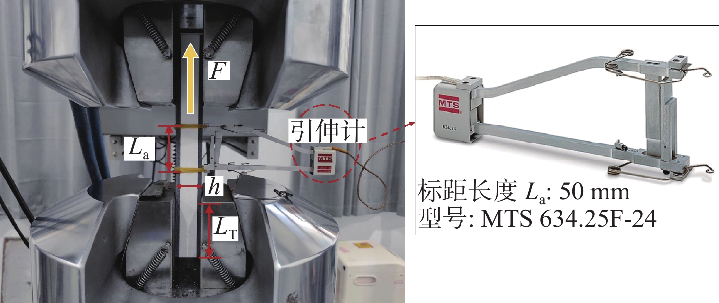
1040.5 -2008测试标准开展组合厚板拉伸试验。组合厚板在垂直筋方向上根据拉伸中心位置的不同可以划分为筋板和泡沫2种,在顺筋方向上根据胞元夹筋数量的不同可以设置单对夹筋和两对夹筋2种,本文将共对上述4种试件开展拉伸试验。设计了4种拉伸试件,其几何尺寸如表5和表6所示,4种拉伸试件如图6所示。试验布置如图7所示。本试验选用高分辨率的引伸计作为变形测量装置,拉力的加载速度为2 mm/min,分别选取6个合格试件进行试验。试件拉伸弹性模量E的计算公式为
表 5 顺筋方向拉伸试件尺寸Table 5. Dimensions of tension specimens in the direction of ribs试件类别 5类 6类 夹筋数量 单对夹筋 两对夹筋 L/\mathrm{m}\mathrm{m} 250 400 b/\mathrm{m}\mathrm{m} 26.25 41.25 h/\mathrm{m}\mathrm{m} 30 30 {L}_{\mathrm{b}}/\mathrm{m}\mathrm{m} 75 75 表 6 垂直筋方向拉伸试件尺寸Table 6. Dimensions of tension specimens in the direction of vertical ribs试件类别 7类 8类 夹筋数量 10对 9对 L/\mathrm{m}\mathrm{m} 250 400 b/\mathrm{m}\mathrm{m} 26.25 41.25 h/\mathrm{m}\mathrm{m} 30 30 {L}_{\mathrm{b}}/\mathrm{m}\mathrm{m} 75 75 E=\frac{\Delta F / S}{\Delta L_{a} / L_{a}} (3) 式中:F为拉伸力;S = bh,为试件截面面积;La为引伸计标距长度,本文取La = 50 mm; \Delta L_{a} 为对应于 \Delta F 的引申计测量段长度增加值。
3. 试验结果与讨论
3.1 组合厚板力学性能分析
图8和图9分别给出了4种弯曲试件在三点弯曲载荷下的峰值载荷。同一种弯曲试件的峰值载荷接近,说明弯曲试验的可重复性好,结果合理可信。从数值上来看,组合厚板在垂直筋方向上的抗弯承载力明显优于顺筋方向。
![]() 图 8 垂直筋方向弯曲试件峰值载荷Figure 8. Peak load of bending specimens in the direction of vertical ribs
图 8 垂直筋方向弯曲试件峰值载荷Figure 8. Peak load of bending specimens in the direction of vertical ribs根据式(1)和式(2)),可获得6组4种弯曲试件的弯曲强度和弯曲刚度如表7和表8所示。其中,表7所示为组合厚板在垂直筋方向弯曲试件的试验结果。经对比可知,组合厚板在垂直筋方向弯曲情况下,相对于三对夹筋,两对夹筋胞元结构的弯曲强度和刚度分别提高了20%和6.8%。这是因为1类试件的初步失效发生在挠度1.9 mm左右,2类试件的初步失效发生在挠度2.0 mm左右,而试件的弯曲强度和刚度由发生失效时的挠度和惯性矩共同决定,故1类试件发生破坏时的挠度更小,这也导致了其弯曲刚度和强度更低。
表 7 组合厚板垂直筋方向弯曲试验结果Table 7. Results of bending test of combined thick plate in the direction of vertical ribs编号 弯曲强度/MPa 弯曲刚度/GPa 编号 弯曲强度/MPa 弯曲刚度/GPa 1-1 187.4 22.6 2-1 219.2 24.4 1-2 138.5 23.1 2-2 195.9 25.9 1-3 147.9 23 2-3 192.6 25.8 1-4 176.1 24.1 2-4 209 24.4 1-5 180.3 24.6 2-5 187.7 25.3 1-6 163.5 22.9 2-6 188.2 24.2 平均值 165.6 23.4 平均值 198.8 25 表 8 组合厚板顺筋方向弯曲试验结果Table 8. Results of bending test of combined thick plate in the direction of ribs编号 弯曲强度/MPa 弯曲刚度/GPa 编号 弯曲强度/MPa 弯曲刚度/GPa 3-1 113.8 21 4-1 95.9 19.6 3-2 107.6 20.8 4-2 75.6 20.1 3-3 100.6 21 4-3 94.5 20.2 3-4 110.7 20.8 4-4 91.8 20.1 3-5 103.8 21.1 4-5 97.4 20.2 3-6 115.8 20.7 4-6 89.2 20.1 平均值 108.7 20.9 平均值 90.7 20 表8所示为组合厚板在顺筋方向弯曲试件的试验结果。经对比可知,组合厚板在顺筋方向弯曲情况下,弯曲中心位置位于筋板中心,相较于泡沫中心,其结构弯曲强度和刚度分别提高了16.6%和4.3%。这是因为两类试件的初步失效均发生在挠度1.2 mm左右,弯曲中心位置处的弯矩载荷最大,泡沫的弹性模量和惯性矩相对于筋板更低,在相同位移情况下,筋板对应的极限载荷更大,因此其弯曲强度和刚度也更大。
由表7和表8的结果可知,组合厚板弯曲中心位置和胞元筋板数量对其弯曲强度的影响较大,对其弯曲刚度的影响较小;组合厚板各向异性显著,其在垂直筋方向的弯曲性能明显高于顺筋方向,弯曲强度提升约82%。
根据式(3)分别计算了4种拉伸试件的拉伸模量,其结果汇总如图10所示。对比5类、6类试件的试验结果可以看出,在顺筋方向上,单筋板和双筋板不同的构型对组合厚板拉伸性能的影响很小,取12组试件的平均值可知,在顺筋方向的拉伸模量为25.8 GPa。对比7类、8类试件的试验结果可以看出,在垂直筋方向上,弯曲中心位置对组合厚板拉伸性能的影响较小,拉伸中心位置为筋板时相对于泡沫,其拉伸模量仅提高了5.3%,计算得到垂直筋方向的拉伸模量为21.15 GPa。可见,组合厚板各向异性显著,其在顺筋方向的拉伸模量比垂直筋方向约高22%。
根据式(4)分别计算了组合厚板试件弯曲强度、弯曲刚度和拉伸模量的离散度,计算结果如表9~表11所示。由表可知,大部分工况下的离散度均在10%以内,弯曲强度的离散度最高仅为10.6%,弯曲刚度的离散度最高仅为3.1%,拉伸模量的离散度最高仅为6.2%。由此可见,本文设计的8种不同构型试件对组合厚板力学性能的研究表明,试验结果误差较小,试验结论合理可信。
表 9 4种弯曲试件弯曲强度离散度Table 9. Dispersion of bending strength for four types of bending specimens试件类别 离散度/% 1类 3.1 2类 2.8 3类 4.9 4类 8.0 表 10 4种弯曲试件弯曲刚度离散度Table 10. Dispersion of bending stiffness for four types of bending specimens试件类别 离散度/% 1类 3.1 2类 2.8 3类 0.7 4类 1.1 表 11 4种拉伸试件拉伸模量离散度Table 11. Dispersion of tensile modulus for four types of tensile specimens试件类别 离散度/% 5类 6.2 6类 2.7 7类 3.8 8类 2.1 V=\frac{\sigma}{R} \times 100 \text{%} (4) 式中:V为离散度; \sigma 为标准差;R为平均值。
在试验过程中发现,组合厚板试件易发生弯曲破坏且破坏形式较为复杂,因此,有必要针对组合厚板弯曲破坏过程展开深入研究。
3.2 组合厚板弯曲破坏过程分析
3.2.1 垂直筋方向弯曲破坏过程分析
针对1类和2类试件,研究胞元筋板数量对组合厚板在垂直筋方向弯曲行为的影响。
1类试件中,选取试件1-1和1-2作为典型代表,介绍两种不同的破坏过程。图11所示为组合厚板1类试件在弯曲载荷下的载荷−挠度曲线图,图12所示为1类试件的弯曲破坏过程图。在加载初期,结构处于弹性阶段,所有试件的载荷−挠度曲线均呈线性增长,在此阶段,硬质泡沫开始产生裂纹,结构未见明显变形(挠度为1.0 mm);当达到峰值载荷后,试件因剪切变形出现下面板局部脱粘破坏(挠度为1.9 mm),曲线第1次出现骤降,承载力大幅降低。继续加载后,试件1-1的下面板一侧完全脱粘(挠度为2.9 mm),试件1-1的曲线第2次骤降,结构被视为完全破坏;之后,下面板在拉力的作用下纤维分层与断裂现象加剧(挠度为8 mm),载荷缓慢下降。试件1-2的破坏过程有所不同(图12(b)),上面板在下面板局部脱粘后紧接着脱粘(挠度为2.3 mm),载荷迅速发生2次下降,之后,同样因为下面板一侧完全脱粘而丧失承载能力。试件1-1和1-2在多个位置出现载荷骤降现象,每一处载荷的骤降均对应于一部分面板的脱粘。针对每个具体的载荷骤降,对应的面板脱粘是瞬间的,从载荷−挠度曲线可知,载荷是骤降而非缓慢降低;而针对整个试件的失效,面板的整体脱粘又是一个渐进的过程,即局部面板先脱粘,此时试件的承载能力虽有降低但仍有相对较强的承载能力,之后,面板一侧完全脱粘,此时试件的承载能力显著降低。
![]() 图 11 弯曲载荷下1类试件的载荷−挠度曲线Figure 11. Load-deflection curves of type 1 specimen under bending load
图 11 弯曲载荷下1类试件的载荷−挠度曲线Figure 11. Load-deflection curves of type 1 specimen under bending load![]() 图 12 组合厚板1类试件的弯曲破坏过程图Figure 12. Bending failure process of type 1 specimen of combined thick plate
图 12 组合厚板1类试件的弯曲破坏过程图Figure 12. Bending failure process of type 1 specimen of combined thick plate2类试件在弯曲载荷下的载荷−挠度曲线如图13所示,图14为2类试件在弯曲荷载下的破坏过程图。6个试件的试验结果一致性较高,其破坏过程与1类试件类似,主要可分为3个阶段:在Ⅰ阶段,载荷随挠度线性增加峰值载荷,试件中部泡沫开始产生明显的裂纹(图14(a));在Ⅱ阶段,载荷出现2次大幅度下降,其原因是下面板发生局部脱粘破坏,并迅速扩展至一侧完全脱粘(图14(b)),结构被视为完全破坏;在Ⅲ阶段,随着挠度的增加载荷缓慢下降,在此阶段在较大横向载荷作用下,泡沫被压碎,面板的纤维分层脱粘和断裂等脆性破坏持续扩展(图14(c)),结构逐渐失去承载能力。
![]() 图 13 弯曲载荷下2类试件的载荷−挠度曲线Figure 13. Load-deflection curves of type 2 specimen under bending load
图 13 弯曲载荷下2类试件的载荷−挠度曲线Figure 13. Load-deflection curves of type 2 specimen under bending load![]() 图 14 组合厚板2类试件的弯曲破坏过程图Figure 14. Bending failure process of type 2 specimen of combined thick plate
图 14 组合厚板2类试件的弯曲破坏过程图Figure 14. Bending failure process of type 2 specimen of combined thick plate对比1类和2类试件的弯曲试验结果可知,在垂直筋方向弯曲载荷作用下,结构初始破坏之前未出现纤维屈曲、断裂等严重的破坏现象,结构破坏主要集中在面板与芯层界面处。结构的初始破坏模式为下面板局部脱粘,继续加载后部分试件呈现出不一样的损伤过程,上面板也发生局部脱粘;试件最终的破坏均由下面板一侧完全脱粘引起。
3.2.2 顺筋方向弯曲破坏过程分析
针对3类和4类试件,研究弯曲中心位置对组合厚板在顺筋方向弯曲行为的影响。
图15所示为组合厚板在顺筋方向弯曲的3类、4类试件载荷−挠度曲线图。图16和图17所示分别为组合厚板3类、4类试件的弯曲破坏过程图。与1类和2类试件不同,3类、4类试件的载荷−挠度曲线特征具有较高的一致性,这说明弯曲中心位置对组合厚板在顺筋方向的弯曲破坏行为影响较小。所有曲线主要可分为2个阶段:在Ⅰ阶段,载荷随着挠度的增加线性增加至峰值;在Ⅱ阶段,随着试件破坏程度的增加,载荷呈台阶状逐步下降。所有试件的初始破坏模式均为筋板剪切破坏(图16(a)、图17(a)),与弯曲中心位置无关,这是因为在弯曲载荷作用下,筋板相较于泡沫刚度更高,使得芯层承受较大的剪切应力且集中在2个筋板胶粘处。随后,部分试件因下面板一侧完全脱粘载荷迅速下降(图16(b)、图17(b)),从而丧失承载力;另一部分试件的下面板未能完全脱粘,随着试件的持续弯曲变形,面板成为主要的承载部分,在剪切力的作用下,面板纤维分层破坏迅速扩展(图16(c)、图17(c)),结构逐渐丧失承载能力。值得注意的是,胶粘剂的强度会影响组合厚板的弯曲破坏模式,但受制于目前胶粘剂的发展,胶粘剂的强度低于夹筋的强度,故组合厚板会先出现脱粘破坏的失效模式。。
![]() 图 15 弯曲载荷下3类、4类试件的载荷−挠度曲线Figure 15. Load-deflection curves of type 3/4 specimen under bending load
图 15 弯曲载荷下3类、4类试件的载荷−挠度曲线Figure 15. Load-deflection curves of type 3/4 specimen under bending load![]() 图 16 组合厚板3类试件的弯曲破坏过程图Figure 16. Bending failure process of type 3 of combined thick plate
图 16 组合厚板3类试件的弯曲破坏过程图Figure 16. Bending failure process of type 3 of combined thick plate![]() 图 17 组合厚板4类试件的弯曲破坏过程图Figure 17. Bending failure process of type 4 of combined thick plate
图 17 组合厚板4类试件的弯曲破坏过程图Figure 17. Bending failure process of type 4 of combined thick plate对比4种构型组合厚板弯曲试件的试验结果,发现在弯曲载荷下,组合厚板在2个方向上的初始破坏均表现出明显的脆断性,且初始破坏模式与弯曲中心位置、胞元筋板数量无关。试件发生初始破坏时,纤维均未出现明显的屈曲、断裂现象,初始破坏位置集中在粘接界面处;试件初始破坏后,承载力严重下降,此时结构可视为基本失效;面板、筋板和泡沫之间的粘接强度在一定程度上决定了结构的弯曲性能。
4. 结 论
本文制备了一种新型泡沫填充的复合材料夹筋夹芯板(组合厚板)结构,通过设计8种不同构型试件,针对顺筋和垂直筋这2个方向分别开展了三点弯曲和拉伸试验,研究了胞元筋板数量和中心位置对其力学性能的影响,主要得到如下结论:
1)组合厚板各向异性显著,在垂直筋方向其弯曲强度约为顺筋方向的1.82倍,在顺筋方向其拉伸模量约为垂直筋方向的1.22倍。胞元筋板数量和加载中心位置对组合厚板弯曲强度影响显著,对拉伸模量影响较小。面板、筋板和泡沫之间的粘接强度一定程度上决定了结构的弯曲强度。
2)在弯曲载荷作用下,组合厚板在垂直筋方向的初始破坏模式为下面板局部脱粘,在顺筋方向的初始破坏模式为筋板剪切破坏。胞元筋板数量和弯曲中心位置对初始破坏模式无明显影响。
3)弯曲试件在初始脱粘破坏后,会呈现出不同的损伤过程。在垂直筋弯曲试件中,试件上面板紧接着下面板会发生局部脱粘破坏,最终破坏均由下面板一侧完全脱粘引起。 在顺筋弯曲试件中,部分试件因下面板一侧完全脱粘而最终破坏;部分试件下面板未能完全脱粘,面板成为主要的承载部分,在加载中逐渐丧失承载能力。
-
![]()
图 1 复合材料夹芯夹筋结构示意图
Figure 1. Schematic diagram of composite plate with reinforcing ribs and core material in the middle
![]()
图 4 组合厚板三点弯曲试验布置图
Figure 4. Layout of three point bending test for combined thick plate
![]()
图 5 4种弯曲试件弯曲示意图
Figure 5. Schematic diagram of bending of four type of bending specimens
![]()
图 8 垂直筋方向弯曲试件峰值载荷
Figure 8. Peak load of bending specimens in the direction of vertical ribs
![]()
图 11 弯曲载荷下1类试件的载荷−挠度曲线
Figure 11. Load-deflection curves of type 1 specimen under bending load
![]()
图 12 组合厚板1类试件的弯曲破坏过程图
Figure 12. Bending failure process of type 1 specimen of combined thick plate
![]()
图 13 弯曲载荷下2类试件的载荷−挠度曲线
Figure 13. Load-deflection curves of type 2 specimen under bending load
![]()
图 14 组合厚板2类试件的弯曲破坏过程图
Figure 14. Bending failure process of type 2 specimen of combined thick plate
![]()
图 15 弯曲载荷下3类、4类试件的载荷−挠度曲线
Figure 15. Load-deflection curves of type 3/4 specimen under bending load
![]()
图 16 组合厚板3类试件的弯曲破坏过程图
Figure 16. Bending failure process of type 3 of combined thick plate
![]()
图 17 组合厚板4类试件的弯曲破坏过程图
Figure 17. Bending failure process of type 4 of combined thick plate
材料 性能 数值 CFRP 纵向弹性模量E1/GPa 125 横向弹性模量E2/GPa 11.3 法向弹性模量E3/GPa 11.3 剪切模量G12,G13,G23/GPa 11.3 泊松比v12,v13,v23 0.3 纵向拉伸强度XT/MPa 2 000 纵向压缩强度XC/MPa 1 000 横向拉伸强度YT/MPa 80 横向压缩强度YC/MPa 280 面外拉伸强度ZT/MPa 42 面外压缩强度ZC/MPa 160 剪切强度S12,S13,S23/MPa 120 BX-700 泡沫弹性模量Efoam/MPa 1 930 泡沫泊松比vfoam 0.329 泡沫密度ρfoam/(kg∙ m−3) 669  下载: 导出CSV
参数 数值 弹性模量E/GPa 2.7 剪切模量G/GPa 2.7 拉伸失效强度σ/MPa 31.5 剪切失效强度τ/MPa 36.5 密度ρ/(kg∙ m−3) 1 100
下载: 导出CSV
表 3 垂直筋方向弯曲试件尺寸
Table 3 Dimensions of bending specimens in the direction of vertical ribs
试件类别 1类 2类 夹筋数量 3对 2对 试件长度L/mm 400 400 试件厚度b/mm 67.5 52.5 试件高度h/mm 30 30 试件宽度Lb/mm 200 200
下载: 导出CSV
表 4 顺筋方向弯曲试件尺寸
Table 4 Dimensions of bending specimens in the direction of ribs
试件类别 3类 4类 弯曲中心位置 筋板中心 泡沫中心 夹筋数量 15对 16对 L/\mathrm{m}\mathrm{m} 382.5 408.5 b/\mathrm{m}\mathrm{m} 60 60 h/mm 30 30 Lb/mm 210 210
下载: 导出CSV
表 5 顺筋方向拉伸试件尺寸
Table 5 Dimensions of tension specimens in the direction of ribs
试件类别 5类 6类 夹筋数量 单对夹筋 两对夹筋 L/\mathrm{m}\mathrm{m} 250 400 b/\mathrm{m}\mathrm{m} 26.25 41.25 h/\mathrm{m}\mathrm{m} 30 30 {L}_{\mathrm{b}}/\mathrm{m}\mathrm{m} 75 75
下载: 导出CSV
表 6 垂直筋方向拉伸试件尺寸
Table 6 Dimensions of tension specimens in the direction of vertical ribs
试件类别 7类 8类 夹筋数量 10对 9对 L/\mathrm{m}\mathrm{m} 250 400 b/\mathrm{m}\mathrm{m} 26.25 41.25 h/\mathrm{m}\mathrm{m} 30 30 {L}_{\mathrm{b}}/\mathrm{m}\mathrm{m} 75 75
下载: 导出CSV
表 7 组合厚板垂直筋方向弯曲试验结果
Table 7 Results of bending test of combined thick plate in the direction of vertical ribs
编号 弯曲强度/MPa 弯曲刚度/GPa 编号 弯曲强度/MPa 弯曲刚度/GPa 1-1 187.4 22.6 2-1 219.2 24.4 1-2 138.5 23.1 2-2 195.9 25.9 1-3 147.9 23 2-3 192.6 25.8 1-4 176.1 24.1 2-4 209 24.4 1-5 180.3 24.6 2-5 187.7 25.3 1-6 163.5 22.9 2-6 188.2 24.2 平均值 165.6 23.4 平均值 198.8 25
下载: 导出CSV
表 8 组合厚板顺筋方向弯曲试验结果
Table 8 Results of bending test of combined thick plate in the direction of ribs
编号 弯曲强度/MPa 弯曲刚度/GPa 编号 弯曲强度/MPa 弯曲刚度/GPa 3-1 113.8 21 4-1 95.9 19.6 3-2 107.6 20.8 4-2 75.6 20.1 3-3 100.6 21 4-3 94.5 20.2 3-4 110.7 20.8 4-4 91.8 20.1 3-5 103.8 21.1 4-5 97.4 20.2 3-6 115.8 20.7 4-6 89.2 20.1 平均值 108.7 20.9 平均值 90.7 20
下载: 导出CSV
表 9 4种弯曲试件弯曲强度离散度
Table 9 Dispersion of bending strength for four types of bending specimens
试件类别 离散度/% 1类 3.1 2类 2.8 3类 4.9 4类 8.0
下载: 导出CSV
表 10 4种弯曲试件弯曲刚度离散度
Table 10 Dispersion of bending stiffness for four types of bending specimens
试件类别 离散度/% 1类 3.1 2类 2.8 3类 0.7 4类 1.1
下载: 导出CSV
表 11 4种拉伸试件拉伸模量离散度
Table 11 Dispersion of tensile modulus for four types of tensile specimens
试件类别 离散度/% 5类 6.2 6类 2.7 7类 3.8 8类 2.1
下载: 导出CSV
-
[1] 朱子旭, 朱锡, 李永清, 等. 复合材料夹芯结构研究 现状及其在船舶工程的应用[J]. 舰船科学技术, 2018, 40(2): 1–7, doi: 10.3404/j.issn.1672-7649.2018.02.001 ZHU Z X, ZHU X, LI Y Q, et al. Present researches about sandwich composite structures and its applies in ship industry[J]. Ship Science and Technology, 2018, 40(2): 1–7 (in Chinese). doi: 10.3404/j.issn.1672-7649.2018.02.001
[2] 周磊, 姚凯, 李会民, 等. 复合材料双向波纹夹层结构力学性能[J]. 复合材料学报, 2021, 38(11): 3661–3671. doi: 10.13801/j.cnki.fhclxb.20210126.001 ZHOU L, YAO K, LI H M, et al. Mechanical properties of composite bi-directional corrugated sandwich structure[J]. Acta Materiae Compositae Sinica, 2021, 38(11): 3661–3671 (in Chinese). doi: 10.13801/j.cnki.fhclxb.20210126.001
[3] STEEVES C A, FLECK N A. Collapse mechanisms of sandwich beams with composite faces and a foam core, loaded in three-point bending. Part II: experimental investigation and numerical modelling[J]. International Journal of Mechanical Sciences, 2004, 46(4): 585–608. doi: 10.1016/j.ijmecsci.2004.04.004
[4] HUANG W, FAN Z H, ZHANG W, et al. Impulsive response of composite sandwich structure with tetrahedral truss core[J]. Composites Science and Technology, 2019, 176: 17–28. doi: 10.1016/j.compscitech.2019.03.020
[5] DUARTE I, TEIXEIRA-DIAS F, GRAÇA A, et al. Failure modes and influence of the Quasi-static deformation rate on the mechanical behavior of sandwich panels with aluminum foam cores[J]. Mechanics of Advanced Materials and Structures, 2010, 17(5): 335–342. doi: 10.1080/15376494.2010.488563
[6] FARROKHABADI A, TAGHIZADEH S A, MADADI H, et al. Experimental and numerical analysis of novel multi-layer sandwich panels under three point bending load[J]. Composite Structures, 2020, 250: 112631. doi: 10.1016/j.compstruct.2020.112631
[7] 赵延杰, 郝轶, 刘建湖, 等. 水下接触爆炸作用下泡沫夹芯板耗能机理研究[J]. 中国舰船研究, 2018, 13(3): 13–22. doi: 10.19693/j.issn.1673-3185.01168 ZHAO Y J, HAO Y, LIU J H, et al. Energy dissipation mechanism of foam sandwich plate subjected to contact underwater explosion[J]. Chinese Journal of Ship Research, 2018, 13(3): 13–22 (in both Chinese and English). doi: 10.19693/j.issn.1673-3185.01168
[8] 陈翀一, 程勇军, 蔡伟, 等. PVC泡沫夹芯板单点低速冲击动态响应与冲击后剩余抗压强度试验研究[J]. 中国舰船研究, 2024, 19(4): 263–270. doi: 10.19693/j.issn.1673-3185.03337 CHEN C Y, CHENG Y J, CAI W, et al. Experimental study on dynamic response and residual compressive strength of composite sandwich panel with PVC foam core under single-point low-velocity impact[J]. Chinese Journal of Ship Research, 2024, 19(4): 263–270 (in both Chinese and English). doi: 10.19693/j.issn.1673-3185.03337
[9] XIONG J, MA L, STOCCHI A, et al. Bending response of carbon fiber composite sandwich beams with three dimensional honeycomb cores[J]. Composite Structures, 2014, 108: 234–242. doi: 10.1016/j.compstruct.2013.09.035
[10] XU G D, ZENG T, CHENG S, et al. Free vibration of composite sandwich beam with graded corrugated lattice core[J]. Composite Structures, 2019, 229: 111466. doi: 10.1016/j.compstruct.2019.111466
[11] SMARDZEWSKI J. Wooden sandwich panels with prismatic core – Energy absorbing capabilities[J]. Composite Structures, 2019, 230: 111535. doi: 10.1016/j.compstruct.2019.111535
[12] KUMAR M, SAINI J S. Computational analysis of bidirectional carbon fibre/epoxy nanocomposites using different failure criteria[J]. Proceedings of the Institution of Mechanical Engineers, Part E: Journal of Process Mechanical Engineering, 2023, 237(4): 1286–1299. doi: 10.1177/09544089221112375
[13] 童浩, 袁昱超, 唐文勇. 新型船用复合材料夹芯夹筋厚板损伤行为分析[J]. 中国舰船研究, 2024, 19(5): 131–140. doi: 10.19693/j.issn.1673-3185.03434 TONG H, YUAN Y C, TANG W Y. Analysis of damage behavior of new-type marine composite thick plate with reinforcing ribs and core material in middle[J]. Chinese Journal of Ship Research, 2024, 19(5): 131–140 (in Chinese). doi: 10.19693/j.issn.1673-3185.03434
[14] 胡春幸, 侯玉亮, 铁瑛, 等. 不同胶接参数对CFRP层合板单搭胶接结构强度的影响及优化设计[J]. 机械工程学报, 2021, 57(8): 154–165. doi: 10.3901/JME.2021.08.154 HU C X, HOU Y L, TIE Y, et al. Influence of different bonding parameters on the strength of CFRP laminates with single lap bonding structure and optimization[J]. Journal of Mechanical Engineering, 2021, 57(8): 154–165 (in Chinese). doi: 10.3901/JME.2021.08.154
[15] 倪士伟. 深海固体浮力材料损伤机理研究[D]. 扬州: 扬州大学, 2018. NI S W. Research on damage mechanism of deep-sea solid buoyancy materials[D]. Yangzhou: Yangzhou University, 2018 (in Chinese).


计量
- 文章访问数: 64
- HTML全文浏览量: 12
- PDF下载量: 0
